HDD PCB Repair
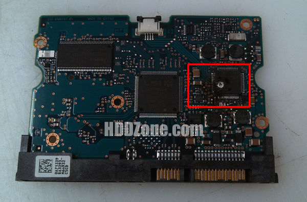
Every HDD should have a PCB. Due to the poor design or poor quality chips, or improper using, the HDD PCB will not work properly. Although there are not much components on the PCB, but the phenomenon of the malfunctions are not less. Such as chips poor contact, Motor Combo IC burnt, etc. Also have some special malfunctions. Different PCB chips had different working way. We need times to check and repair.

Now we introduce the methods of how to judge the special malfunctions:
- 1. Check are there any components off PCB. If you find some components lost, you should add them on the PCB.
Are there any components in poor contact? If yes, you should add more tin to weld them well.
Are there any components be burnt? If yes, you should change the components. - 2. Touch the PCB by hands to check the components are hot or not. The PCB is unusual hot, it means the voltage is high or components shorted out. No temperature means the components are not working. We should test the voltage is normal or not by using a multimeter.
- 3. Connect the PCB with power and check the indicator light. Flashed once, it means the Main Controller IC was damaged. Week flash, but the voltage is normal, it also means the Main Controller IC was damaged. Week light, but the voltage is normal, it means both the Main Controller IC and the Motor Combo IC are damaged.
- 4. In normal, EL, CR,EX,CX lights should flash 6 times. Others should flash 10 times. Only flash 5 times, it means the cash in poor contact/ damaged; also can be caused by Main Controller IC in poor contact/damaged.
All the PCB problems can be resolved by swapping PCB. First you should find a matching PCB. Also you should to know most PCB swapping should be exchange the BIOS/Main Controller IC before you swap hard drive PCB, in order to make the replacement board compatible with your HDD. You can move the BIOS from your original PCB by using hot-air gun, then solder it on the replacement board. Or you can find the electronics repair shop to help you.


